

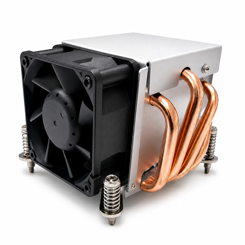
Model 104-0046-1 is our 2U server heat sink, combining a copper heat-pipe structure with a high-static-pressure fan for dense rack systems. The extra height over a 1U part lets us raise dissipation capacity and lower acoustic output at the same time. This guide covers specifications, installation, maintenance, troubleshooting and selection.
What Changes When You Move From 1U to 2U
2U gives you 3.5 inches (88.9 mm) of vertical space instead of 1.75 inches. That extra room changes the thermal design in three useful ways:
- More fin surface area. A taller stack means more fins at the same pitch, so the same airflow removes more heat.
- Larger fan diameter. A bigger fan moves the same air volume at lower RPM, which drops noise substantially.
- Heat pipes become viable. A heat-pipe design spreads heat laterally across the whole fin stack, so the fin area away from the fan exit is not wasted. In a 1U part you rarely have the height budget for an effective pipe run.
Technical Specifications of Model 104-0046-1
| Parameter | Specification |
|---|---|
| Model | 2U heatsink 104-0046-1 |
| Overall Dimension | 90 × 88 × 66 mm |
| Weight | 326 g |
| TDP | 125 W |
| Heat Pipe Structure | 4 copper heat pipes |
| Fin Count | 34 fins |
| Base Material | Copper (Cu) |
| Surface Treatment | Nickel plated |
| Top Cover | Aluminium |
| Fan Dimension | 60 × 60 × 25 mm |
| Fan Blades | 7 blades / black |
| Rated Voltage / Current | 12 V DC / 0.66 A |
| Power Consumption | 7.92 W |
| Fan Speed | 7000 RPM ±10% (PWM) |
| Bearing Type | Two ball bearing |
| Fan Life | 70,000 hours (30 °C, 15–65% RH) |
| Static Pressure | 16.05 mmH2O (MAX) |
| Air Flow | 32.65 CFM (MAX) |
| Noise | 49.55 dBA |
| Connector | 2.54-4Pin PWM |
| CPU Compatibility | Socket 115X / 1700 |
| Package | 465 × 352 × 223 mm, 24 pcs, 9 kg net |
Note the design choices behind the numbers. The nickel-plated copper base resists oxidation and keeps the thermal interface stable over years of service — bare copper gradually forms oxide layers that add contact resistance. The 125 W TDP rating is roughly a third higher than our 1U part, because the heat pipes do the spreading work that fins alone cannot in a comparable height.
Air flow more than triples versus the 1U model (32.65 vs 10.57 CFM). That is the practical benefit of 2U: you are no longer fighting back pressure with a 75 mm fan limited to a 16 mm depth.
Installation Guide: Step-by-Step
- Power down the node and remove it from the rack if the chassis requires top access. Working on a partially withdrawn server risks bending the retention mechanism.
- Inspect the heat pipes before installation. A heat pipe that has been pinched or kinked in shipping is thermally dead — the working fluid cannot return to the evaporator. Reject any part with a visible deformation.
- Clean both mating surfaces with isopropyl alcohol. The nickel-plated base should show a uniform matte finish, with no cloudiness or residue.
- Apply TIM as a thin central line or pea dot. With a copper base the spread is forgiving, but excess still leaks onto the socket.
- Seat and fasten diagonally. Bring the screws down in opposite-corner pairs. Heat-pipe bases are stiffer than solid aluminium and will not conform to a tilted socket, so even pressure matters more here.
- Connect PWM to the CPU_FAN header. Verify tachometer feedback in the BIOS or BMC.
- Confirm thermal margins with a sustained load test and, where the BMC supports it, log inlet and CPU temperatures to establish a baseline for future comparison.
Maintenance & Cleaning
Heat-pipe and dense-fin assemblies collect dust faster than open extruded profiles because the fin pitch is tighter. Recommended practice:
- Every 6 months in a filtered data centre; every 3 months in an unfiltered or workshop environment.
- Use compressed air at low pressure, directed along the fin channels rather than perpendicular to them — blowing across the fins drives debris deeper into the stack.
- Hold the fan blades still while cleaning. Spinning a ball-bearing fan with compressed air can exceed its rated RPM and damage the bearing races.
- Never use solvents on the nickel plating; a dry soft brush plus air is sufficient.
- Log post-cleaning temperatures. A drop of more than a few degrees confirms dust was the limiting factor and may justify shortening the interval.
Common Issues & Troubleshooting
| Symptom | Likely Cause | Corrective Action |
|---|---|---|
| Temperature rises steadily over weeks | Dust in a tight fin stack | Clean along fin channels with low-pressure air |
| One side of the stack runs hot | Kinked or dry heat pipe | Replace the heat sink — pipes cannot be repaired in the field |
| Fan ramps to 100% immediately | Inlet air restriction or failed chassis fan | Check the chassis airflow path before blaming the heat sink |
| Audible bearing whine | Ball bearing wear approaching end of life | Schedule fan replacement; keep a spare on site |
| High idle temperature after service | TIM not re-applied or excessive TIM | Re-clean and re-apply; verify even retention pressure |
| Throttling only on one node in a rack | Localised hot aisle / recirculation | Investigate rack-level airflow, not the component |
Comparison with Other Server Cooling Solutions
| Solution | TDP | Height | Best Fit |
|---|---|---|---|
| 2U copper heat pipe (104-0046-1) | 125 W | 66 mm | 2U rack servers where per-node capacity matters |
| 1U skiving fin (103-0011-1) | 95 W | 29 mm | Dense 1U fleets with strict height limits |
| 3U skiving fin (107-0033-1) | 95 W | 29 mm | 1U/3U hybrid platforms needing 5000 RPM pressure |
| Passive extruded heat sink | 35–65 W | Variable | Low-power nodes with strong chassis airflow |
| Liquid cooling | 150 W+ | Pump + radiator | Highest-density compute where a pump is acceptable |
Selection Checklist
- Verified 66 mm clearance including socket and gasket stack-up.
- CPU TDP at or below 125 W, with headroom for turbo bursts.
- Socket compatibility confirmed (115X / 1700).
- Chassis airflow direction matched to the fin channel orientation — a heat sink mounted across the airflow axis loses a large fraction of its rated performance.
- Spare fan units stocked, since the fan is the only moving part and therefore the only wear item.
OEM / ODM Customization
The 104-0046-1 platform supports customization in heat pipe count and diameter, fin pitch, base dimensions, mounting pattern and fan specification. We handle requirement analysis, engineering design, sample testing and mass production in-house.
Contact our engineering team with your chassis drawing and thermal target to begin an OEM/ODM evaluation.