

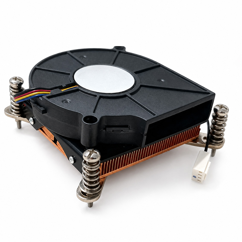
Model 103-0011-1 is our ultra-low-profile 1U server heat sink, built for rack-mount and edge systems where vertical clearance is measured in a few millimetres. This guide consolidates everything we know about the part — specifications, installation, maintenance, troubleshooting, and how it compares with alternative 1U cooling approaches.
What Is a 1U Heat Sink?
In rack-mount terminology, 1U equals 1.75 inches (44.45 mm) of vertical height. Inside that envelope you have to fit a CPU, a socket, retention hardware, memory and a heat sink — while still leaving clearance for airflow. That is why 1U cooling is a different engineering problem from tower PC cooling: there is no room for a tall fin stack, so the design has to win on fin density, base material and static pressure rather than on sheer size.
Model 103-0011-1 solves this with a skiving fin construction — a manufacturing method that slices fins directly out of a solid aluminium block, producing a one-piece base and fin structure with no thermal interface between them.
Technical Specifications of Model 103-0011-1
| Parameter | Specification |
|---|---|
| Model | 1U heat sink 103-0011-1 |
| Overall Dimension | 89 × 89 × 29 mm |
| Weight | 309 g |
| TDP | 95 W |
| Fin Construction | Skiving (one-piece base + fins) |
| Fin Count | 51 fins |
| Base Material | SKIVING aluminium |
| Surface Treatment | Passivation |
| Fan Dimension | 75 × 75 × 16 mm |
| Fan Blades | 21 blades / black |
| Rated Voltage / Current | 12 V DC / 0.52 A |
| Power Consumption | 6.24 W |
| Fan Speed | 5000 RPM ±10% (PWM) |
| Bearing Type | Two ball bearing |
| Fan Life | 70,000 hours |
| Static Pressure | 36.29 mmH2O (MAX) |
| Air Flow | 10.57 CFM (MAX) |
| Noise | 50 dBA |
| Connector | 2.54-4Pin PWM |
| CPU Compatibility | Socket 115X / 1700 |
| Package | 410 × 310 × 125 mm, 24 pcs, 8.7 kg net |
Two numbers matter most here. The 29 mm total height is what makes it a true 1U part, and the 36.29 mmH2O static pressure is unusually high for a 75 mm fan — that is deliberate. In a 1U chassis the airflow path is obstructed by memory modules, risers and drive cages, so the fan must push through back pressure rather than free-blow. Air flow (10.57 CFM) is modest by design; pressure is what keeps air moving across those 51 fins.
The two ball bearing and 70,000-hour rating are aimed at continuous-duty operation. A sleeve or hydraulic bearing may be quieter in a desktop, but it is the wrong choice for a server that runs 24/7 in a hot rack.
Why 1U Servers Need Dedicated Thermal Management
Heat in a dense chassis causes four specific failures, and each has a measurable cost:
- Thermal throttling. When the CPU approaches its junction temperature limit, it reduces clock speed to protect itself. You lose throughput exactly when load is highest.
- Accelerated component degradation. Capacitors, VRM stages and solder joints all age faster under sustained high temperature. Many degradation rates roughly double for every 10 °C rise.
- Unexpected shutdowns. Servers carry thermal fail-safes that cut power above a threshold. That is an availability incident, not a performance dip.
- Higher facility cooling load. Poor die-level heat extraction pushes more heat into the room, which the CRAC units must then remove — you pay for the same watt twice.
A properly specified heat sink attacks the problem at the source: it reduces case-to-ambient thermal resistance, so the fan does not have to work as hard and the room does not have to absorb as much.
Installation Guide: Step-by-Step
- Power down and discharge. Remove power, wait for the PSU to bleed, and ground yourself. Never work on a live board.
- Clean the CPU and heat sink base. Remove all old thermal interface material with isopropyl alcohol (90%+). Both surfaces must be bright and dry — residue is the single most common cause of a bad mount.
- Apply thermal interface material. A pea-sized dot in the centre of the IHS is sufficient. Do not spread it manually; mounting pressure does that. Excess paste squeezes out and can bridge nearby contacts.
- Seat the heat sink. Lower it vertically. Do not slide it sideways after contact — that traps air and creates voids.
- Tighten in a diagonal pattern. Bring the fasteners down gradually, alternating opposite corners, until seated. Fully tightening one side first tilts the base and produces uneven contact pressure.
- Connect the PWM fan header. Use the CPU_FAN header so the BIOS can read tachometer feedback and trigger a thermal alarm if the fan stops.
- Verify in BIOS. Confirm the fan reports an RPM and that idle temperature sits in the expected range before closing the chassis.
- Run a load test. Apply a sustained workload for at least 15 minutes and watch for throttling. A rising curve that plateaus is healthy; a continuous climb is not.
Common Issues & Troubleshooting
| Symptom | Likely Cause | Corrective Action |
|---|---|---|
| CPU throttles under load | Airflow obstruction or oversized TIM layer | Clear cable routing; re-seat with a thinner TIM application |
| Fan not spinning / no RPM | Header not connected or set to DC mode in BIOS | Move to CPU_FAN, set the header to PWM mode |
| Noisy operation at idle | Fan curve too aggressive | Enable PWM control and set a minimum duty floor near 30% |
| High idle temperature | Poor base contact or dried TIM | Clean and re-apply TIM; check retention pressure is even |
| Gradual temperature rise over months | Dust accumulation across the fin stack | Clean with compressed air every 6–12 months in dusty environments |
| Temperature spikes and drops | Intermittent fan bearing wear | Replace fan; ball bearings wear audibly before they fail |
How 103-0011-1 Compares to Other 1U Cooling Solutions
| Approach | Typical TDP | Height Profile | Trade-off |
|---|---|---|---|
| Skiving fin + high-pressure fan (103-0011-1) | 95 W | ~29 mm | Best pressure-to-height ratio; highest noise of the group |
| Extruded aluminium heat sink, passive | 35–65 W | ~25 mm | Silent and cheap, but relies on substantial chassis airflow |
| Copper heat pipe + folded fin | 95–125 W | ~40 mm+ | Higher capacity, but exceeds a true 1U envelope |
| Liquid cooling loop | 150 W+ | Requires pump + radiator | Best raw capacity; adds a pump as a single point of failure |
The practical conclusion: if you are locked to a genuine 1U envelope and need around 95 W of dissipation, the skiving-fin approach is the correct answer. If you can spare 2U of height, a copper heat-pipe design such as our 2U heatsink 104-0046-1 will deliver the same cooling at lower acoustic cost.
Role in Data Centers
In a data centre, a server heat sink is not a component — it is an availability control. Two effects matter at fleet scale:
- Thermal headroom buys scheduling flexibility. A processor running 15 °C below its limit can absorb workload spikes without dropping frequency, which matters when you are bin-packing virtual machines onto hosts.
- Cooling efficiency compounds across the fleet. A one-degree improvement in die-to-ambient performance, multiplied across hundreds of nodes and 8,760 hours a year, becomes a material line item in the power budget.
Selection Checklist
- Confirm available vertical clearance — 29 mm must fit with the socket and retention hardware accounted for.
- Confirm CPU TDP does not exceed 95 W, or de-rate accordingly.
- Confirm socket compatibility (115X / 1700 for this model).
- Confirm the chassis provides ambient airflow; a 1U heat sink is not a substitute for chassis-level air movement.
- Plan a dust-cleaning interval appropriate to the environment — this is the most commonly skipped maintenance step and the most common cause of rising temperatures.
OEM / ODM Customization
Model 103-0011-1 is available with customization across fin pitch, base dimensions, mounting pattern, fan selection and finish. Our process runs from requirement analysis through engineering design, sample testing and mass production. If you need a variant tuned to a specific chassis or thermal target, send us the mechanical drawing and target TDP.
Request a quotation or a sample — contact our engineering team with your specification.