

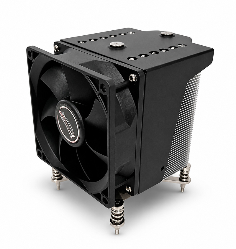
Model 107-0033-1 is a skiving-fin server heat sink specified for both 1U and 3U platforms, using a 5000 RPM dual-ball-bearing fan to push air through a 51-fin stack in high-density enclosures. This guide covers its specifications, thermal behaviour, installation, maintenance and how it positions against other server cooling options.
Skiving Fin Technology Explained
Most entry-level heat sinks are extruded: aluminium is pushed through a die to form a profile with fins already attached. Extrusion is cheap, but it limits you to relatively thick fins and a coarse pitch, because the die has to withstand the forming pressure.
Skiving works differently. A cutting tool slices through a solid aluminium block, peeling up a fin and leaving it attached to the base as one continuous piece of metal. That gives three advantages:
- Higher fin density. 51 fins in an 89 × 89 mm footprint, versus what an extrusion can achieve in the same area.
- No bond-line resistance. Base and fins are the same piece of aluminium, so there is no solder or epoxy interface adding thermal resistance between them.
- Better fin aspect ratio. Skived fins can be made taller and thinner, raising surface area without proportionally raising weight.
The trade-off is tooling cost and a base that is inherently a fixed geometry — which is why custom skived designs are usually an OEM project rather than a catalogue variation.
Technical Specifications of Model 107-0033-1
| Parameter | Specification |
|---|---|
| Model | 3U heatsink 107-0033-1 |
| Overall Dimension | 89 × 89 × 29 mm |
| Weight | 309 g |
| TDP | 95 W |
| Fin Construction | Skiving |
| Fin Count | 51 fins |
| Base Material | SKIVING aluminium |
| Surface Treatment | Passivation |
| Fan Dimension | 75 × 75 × 16 mm |
| Fan Blades | 21 blades / black |
| Rated Voltage / Current | 12 V DC / 0.52 A |
| Power Consumption | 6.24 W |
| Fan Speed | 5000 RPM ±10% (PWM) |
| Bearing Type | Two ball bearing |
| Fan Life | 70,000 hours |
| Static Pressure | 36.29 mmH2O (MAX) |
| Air Flow | 10.57 CFM (MAX) |
| Noise | 50 dBA |
| Connector | 2.54-4Pin PWM |
| CPU Compatibility | Socket 115X / 1700 |
| Package | 410 × 310 × 125 mm, 24 pcs, 8.7 kg net |
Read the specification as a system rather than a list. The 36.29 mmH2O static pressure is the defining number: this fan is selected to overcome the obstruction inside a populated server chassis, not to maximise free-air CFM. The low air-flow figure (10.57 CFM) is the direct consequence — a 75 × 16 mm fan cannot deliver both high pressure and high free-air volume, and for a server the pressure term is the one that determines whether air actually reaches the fins.
The passivation surface treatment forms a thin protective oxide layer that inhibits corrosion without the dimensional change of plating. For an aluminium part that will live in a humid rack for years, that matters.
High-Density Cooling: Why It Matters
Three effects drive temperature in a high-density rack, and a heat sink only addresses one of them directly — which is why selection has to consider all three:
- Die-level heat flux. Modern processors concentrate 95 W into a small area. The heat sink's job is to spread that flux across enough surface that air can carry it away. Skiving helps here through the continuous metal path.
- Internal chassis recirculation. Air that has already passed over one component arrives at the next one warmer. High static pressure helps push through this rather than stalling.
- Facility inlet temperature. No heat sink can cool below the temperature of the air it receives. Every degree of hot-aisle recirculation is a degree added to the CPU.
Installation Guide: Step-by-Step
- Confirm the platform. This part is specified for 1U/3U server platforms with socket 115X or 1700. Verify before disassembly.
- Power down and ground yourself. Observe standard ESD precautions.
- Remove old TIM completely. Use isopropyl alcohol and a lint-free wipe until the IHS and heat sink base are uniformly clean.
- Apply fresh TIM. A central dot sized to roughly a grain of rice. Passivated aluminium is slightly more sensitive to excess paste than a copper base — keep the layer thin.
- Seat vertically and fasten diagonally. Alternate opposite corners to load the base evenly.
- Connect the 4-pin PWM header to CPU_FAN. Configure the fan curve so idle duty sits around 30–40% — at 5000 RPM this fan is loud at 100%, and there is no reason to run it there at idle.
- Baseline the temperatures. Record idle and sustained-load values. Without a baseline, a future gradual rise is invisible.
Maintenance Schedule
| Interval | Action | Why |
|---|---|---|
| Monthly | Check BMC/BIOS for fan RPM anomalies | Detects bearing wear before it becomes a thermal event |
| Quarterly (dusty) | Clean fins with low-pressure air along the channels | Tight fin pitch traps dust that acts as an insulator |
| Semi-annual (filtered DC) | Full clean and temperature baseline comparison | Confirms the cooling system still performs to specification |
| Annually | Inspect retention hardware and TIM condition | Thermal paste degrades; mounting pressure can relax over thermal cycles |
| Annually | Review fan life against the 70,000-hour rating | Plan replacement before failure rather than after |
Common Issues & Troubleshooting
| Symptom | Likely Cause | Corrective Action |
|---|---|---|
| Fan reports 0 RPM | Bearing seizure or disconnected header | Check the connector first, then replace the fan |
| Progressive temperature increase | Dust in the 51-fin stack | Clean along fin channels; re-baseline afterwards |
| Noisy at idle | Fan curve running the 5000 RPM fan at full duty | Set a PWM floor of 30–40% in BIOS or BMC |
| Throttling at high ambient only | Facility inlet temperature above design | Address rack airflow; the heat sink is not the limiting factor |
| Uneven fin temperatures | Airflow misaligned with fin channels | Rotate the heat sink or adjust ducting to match the airflow axis |
| Retention hardware loosening | Thermal cycling over long service | Re-torque diagonally to specification; inspect for deformation |
Comparison with Other Server Cooling Solutions
| Model / Approach | TDP | Fan | Pressure | Notes |
|---|---|---|---|---|
| 107-0033-1 skiving fin | 95 W | 75 mm, 5000 RPM | 36.29 mmH2O | Highest pressure; best for obstructed 1U/3U paths |
| 103-0011-1 skiving fin | 95 W | 75 mm, 5000 RPM | 36.29 mmH2O | Same thermal core, 1U-optimised variant |
| 104-0046-1 copper heat pipe | 125 W | 60 mm, 7000 RPM | 16.05 mmH2O | Higher TDP, larger heat-spreading capability |
| Passive extrusion | 35–65 W | None | — | Silent; depends entirely on chassis airflow |
Selection Checklist
- Vertical clearance verified at 29 mm plus socket and retention stack-up.
- TDP at or below 95 W.
- Socket confirmed (115X / 1700).
- Chassis airflow axis aligned with the fin channels.
- PWM fan curve configured — do not run a 5000 RPM fan at fixed full duty.
- Dust interval defined for the deployment environment and logged.
OEM / ODM Customization
Skived heat sinks are inherently custom-friendly on the tooling side once the die is made, which makes them a good fit for OEM programmes with a fixed chassis. We can adapt fin count and pitch, base footprint, mounting pattern and fan selection, and we run the full cycle from requirement analysis through sample testing to mass production.
Send us your mechanical drawing and target TDP to start a custom evaluation.